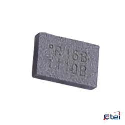
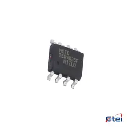
Abbildungen dienen nur als Referenz
AD711JRZ
+StücklisteIC OPAMP JFET 1 CIRCUIT 8SOIC
-
HerstellerAnalog Devices Inc.
-
Herstellerteil #AD711JRZ
-
Datenblatt AD711JRZ DataSheet
-
Paket SOP8
-
Auf Lager3081
365 Tage Qualitätsgarantie
7*24 Stunden-Servicegarantie
90-Tage Kundendienstgarantie
Originalproduktgarantie
Spezifikationen
| Attribut | Wert |
| Package | Bulk,Tube |
| ProductStatus | Active |
| AmplifierType | J-FET |
| NumberofCircuits | 1 |
| SlewRate | 20V/µs |
| -3dbBandwidth | 4 MHz |
| Current-InputBias | 15 pA |
| Voltage-InputOffset | 300 µV |
| Current-Supply | 2.5mA |
| Current-Output/Channel | 25 mA |
| Voltage-SupplySpan(Min) | 9 V |
| Voltage-SupplySpan(Max) | 36 V |
| OperatingTemperature | 0°C ~ 70°C |
| MountingType | Surface Mount |
| Package/Case | 8-SOIC (0.154, 3.90mm Width) |
Übersicht
Description
Equivalent
Features
1. Low Noise: It offers a low noise performance of 7 nV/√Hz, making it suitable for applications requiring low-level signal amplification.
2. High Slew Rate: The slew rate is 16 V/μs, enabling fast response times which is beneficial for high-speed signal processing.
3. Wide Bandwidth: With a unity-gain bandwidth of 4 MHz, it supports a broad range of frequencies for various applications.
4. Low Input Offset Voltage: It features a low input offset voltage of 0.3 mV, enhancing accuracy in precision tasks.
5. Low Input Bias Current: The input bias current is 50 nA, minimizing error in high-impedance circuits.
6. Dual Supply Operation: The AD711JRZ operates with dual power supplies ranging from ±5 V to ±18 V, providing flexibility in different circuit designs.
7. Temperature Range: It functions reliably over a temperature range of 0°C to +70°C, suitable for various environmental conditions.
These features make the AD711JRZ ideal for applications in instrumentation, data acquisition systems, and precision controls.
Pinout
1. Pin 1 (Offset Null 1): Used for offset voltage adjustment.
2. Pin 2 (Inverting Input - IN−): Inverting input terminal of the amplifier.
3. Pin 3 (Non-inverting Input - IN+): Non-inverting input terminal of the amplifier.
4. Pin 4 (V−): Negative power supply terminal.
5. Pin 5 (Offset Null 2): Used for offset voltage adjustment.
6. Pin 6 (Output): The output terminal of the amplifier.
7. Pin 7 (V+): Positive power supply terminal.
8. Pin 8 (NC or No Connect): Typically not connected internally, used for mechanical stability.
The AD711JRZ is used in applications requiring precision amplification, and it offers high slew rate and low input offset voltage, ideal for signal conditioning and instrumentation.
Manufacturer
Application
1. Data Acquisition Systems: Utilized for its fast settling time and precision in processing analog signals.
2. Signal Conditioning: Ideal for buffering and amplifying signals in sensors and instrumentation.
3. Active Filters: Employed in designing high-performance active filter circuits.
4. Audio Processing: Used in audio equipment for high-fidelity sound reproduction.
5. Medical Instruments: Applicable in medical devices requiring precise and reliable signal amplification.
6. Test Equipment: Essential in oscilloscopes and waveform generators for accurate signal processing.
These applications leverage the AD711JRZ's stability, low input bias current, and excellent noise performance.