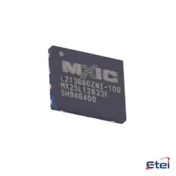
Abbildungen dienen nur als Referenz
ADC121S021CIMFX/NO
+Stückliste-
HerstellerTexas Instruments
-
Herstellerteil #ADC121S021CIMFX/NO
-
Auf Lager3994
365 Tage Qualitätsgarantie
7*24 Stunden-Servicegarantie
90-Tage Kundendienstgarantie
Originalproduktgarantie
Spezifikationen
| Attribut | Wert |
| Brand | Texas Instruments |
| Product Type | ADCs - Analog to Digital Converters |
| Subcategory | Data Converter ICs |
Übersicht
Description
The ADC121S021CIMFX/NO is a 12-bit analog-to-digital converter (ADC) designed for low-power, high-speed applications. It features a single-channel input and operates with a supply voltage ranging from 2.7V to 5.5V. The device offers a maximum sampling rate of 1 MSPS (mega samples per second), making it suitable for various applications in data acquisition, industrial control, and portable devices.
Key features include a serial peripheral interface (SPI) for easy data communication, a low power consumption mode, and an internal reference voltage, simplifying the design process. The ADC121S021CIMFX/NO is packaged in a compact 16-pin TSSOP format, making it ideal for space-constrained applications.
With its high resolution and fast conversion capabilities, the ADC121S021CIMFX/NO is an excellent choice for those needing reliable analog signal processing in modern electronic systems.
Key features include a serial peripheral interface (SPI) for easy data communication, a low power consumption mode, and an internal reference voltage, simplifying the design process. The ADC121S021CIMFX/NO is packaged in a compact 16-pin TSSOP format, making it ideal for space-constrained applications.
With its high resolution and fast conversion capabilities, the ADC121S021CIMFX/NO is an excellent choice for those needing reliable analog signal processing in modern electronic systems.
Equivalent
Equivalent products to the ADC121S021CIMFX/NO chip include the MCP3201, ADS1015, and LTC1865. These alternatives offer similar specifications such as resolution, sampling rate, and interface options for analog-to-digital conversion. Always check datasheets for specific requirements and compatibility before substitution.
Features
The ADC121S021CIMFX/NO is a 12-bit analog-to-digital converter (ADC) featuring a single-channel input. Key features include:
1. Resolution: 12-bit, providing 4096 discrete output levels.
2. Sampling Rate: Capable of sampling at rates up to 1 Msps (mega samples per second).
3. Input Voltage Range: Typically operates within 0 to VREF (reference voltage).
4. Interface: Serial interface (SPI-compatible) for easy integration with microcontrollers.
5. Low Power Consumption: Designed for low power operation, ideal for battery-powered applications.
6. Self-Calibration: Includes a self-calibration feature for improved accuracy.
7. Temperature Range: Operational across a wide temperature range suitable for various environments.
8. Single Supply Operation: Can be powered with a single supply voltage, simplifying design.
These features make the ADC121S021CIMFX/NO suitable for precision measurement applications in industrial, automotive, and consumer electronic devices.
1. Resolution: 12-bit, providing 4096 discrete output levels.
2. Sampling Rate: Capable of sampling at rates up to 1 Msps (mega samples per second).
3. Input Voltage Range: Typically operates within 0 to VREF (reference voltage).
4. Interface: Serial interface (SPI-compatible) for easy integration with microcontrollers.
5. Low Power Consumption: Designed for low power operation, ideal for battery-powered applications.
6. Self-Calibration: Includes a self-calibration feature for improved accuracy.
7. Temperature Range: Operational across a wide temperature range suitable for various environments.
8. Single Supply Operation: Can be powered with a single supply voltage, simplifying design.
These features make the ADC121S021CIMFX/NO suitable for precision measurement applications in industrial, automotive, and consumer electronic devices.
Pinout
The ADC121S021CIMFX/NO is a 12-bit analog-to-digital converter (ADC) with a total of 16 pins. Its primary functions include converting analog signals into digital data, with a sampling rate of up to 1 MSPS (mega samples per second).
### Pin Count and Functions:
1. VREF: Reference voltage input.
2. AGND: Analog ground.
3. AVDD: Analog supply voltage.
4. DVDD: Digital supply voltage.
5. SCL: Serial clock input (for communication).
6. SDA: Serial data input/output (I²C interface).
7. CS: Chip select input.
8. ALERT: Alert output flag.
9. VIN+: Positive analog input.
10. VIN-: Negative analog input or ground.
11. MODE: Mode select pin.
12. PD: Power-down pin.
13. SCK: Serial clock (for SPI communication).
14. DOUT: Data output.
15. DIN: Data input.
16. MISO: Master In Slave Out (SPI communication).
This configuration allows for versatile interfacing with microcontrollers and other digital systems.
### Pin Count and Functions:
1. VREF: Reference voltage input.
2. AGND: Analog ground.
3. AVDD: Analog supply voltage.
4. DVDD: Digital supply voltage.
5. SCL: Serial clock input (for communication).
6. SDA: Serial data input/output (I²C interface).
7. CS: Chip select input.
8. ALERT: Alert output flag.
9. VIN+: Positive analog input.
10. VIN-: Negative analog input or ground.
11. MODE: Mode select pin.
12. PD: Power-down pin.
13. SCK: Serial clock (for SPI communication).
14. DOUT: Data output.
15. DIN: Data input.
16. MISO: Master In Slave Out (SPI communication).
This configuration allows for versatile interfacing with microcontrollers and other digital systems.
Manufacturer
The ADC121S021CIMFX/NO is manufactured by Texas Instruments (TI). Founded in 1930, Texas Instruments is a global semiconductor design and manufacturing company headquartered in Dallas, Texas. The company specializes in analog and embedded processing technologies, serving a variety of industries including automotive, industrial, consumer electronics, and communications. Texas Instruments is well-known for its innovative products, including analog-to-digital converters (ADCs), digital signal processors (DSPs), microcontrollers, and power management devices. Additionally, TI is a prominent provider of integrated circuits (ICs) and plays a significant role in advancing technologies such as the Internet of Things (IoT) and automation.
Application
The ADC121S021CIMFX/NO is a 12-bit analog-to-digital converter (ADC) primarily used in applications such as industrial process control, medical instrumentation, portable instrumentation, and sensor monitoring. Its low power consumption and fast conversion rate make it suitable for battery-operated devices and remote sensing applications. It is also utilized in data acquisition systems, audio processing, and portable medical devices, allowing for accurate and efficient signal digitization in various environments.
Package
The ADC121S021CIMFX/NO is packaged in a 16-pin TSSOP (Thin Shrink Small Outline Package). This compact package type is designed for surface mounting, providing a space-efficient solution for applications requiring analog-to-digital conversion.