
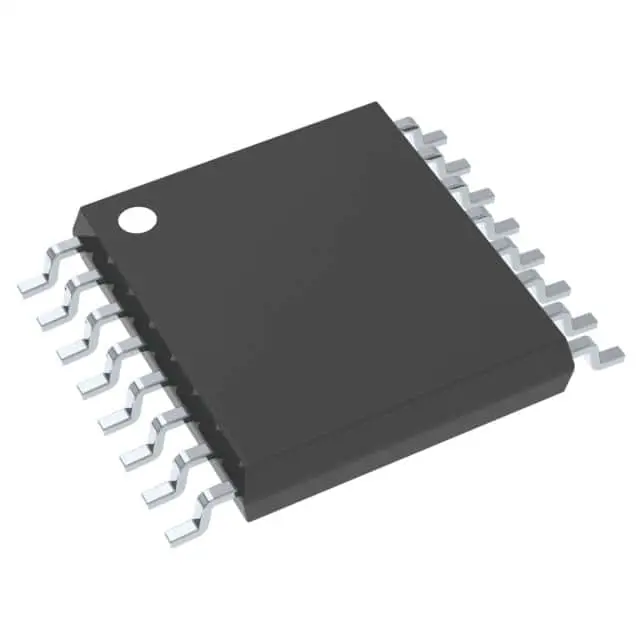
Abbildungen dienen nur als Referenz





IC MULTIVIBRATOR 25NS 16TSSOP
-
HerstellerTexas Instruments
-
Herstellerteil #CD74HC123PWR
-
Paket TSSOP-16
-
Auf Lager7086
365 Tage Qualitätsgarantie
7*24 Stunden-Servicegarantie
90-Tage Kundendienstgarantie
Originalproduktgarantie
Spezifikationen
| Attribut | Wert |
| Package / Case | Tape & Reel (TR),Cut Tape (CT) |
| Series | 74HC |
| Part Status | Active |
| Logic Type | Monostable |
| Independent Circuits | 2 |
| Schmitt Trigger Input | No |
| Propagation Delay | 25 ns |
| Current - Output High Low | 5.2mA, 5.2mA |
| Voltage - Supply | 2 V ~ 6 V |
| Operating Temperature | -55°C ~ 125°C |
| Mounting Type | Surface Mount |
Übersicht
Description
Each multivibrator in the CD74HC123PWR can be independently controlled, with external resistors and capacitors setting the pulse width. It includes input clamping diodes, allowing for simple interfacing to TTL logic levels, and Schmitt-trigger action on the inputs enhances noise immunity, ensuring reliable operation in noisy environments.
The device is available in a TSSOP package (PWR suffix), making it compact and suitable for applications where space is a concern. Its wide range of applications includes pulse stretching, delay timing, pulse generation, and timing applications in various electronic circuits.
Equivalent
1. 74HC123 by NXP
2. SN74HC123 by Texas Instruments
3. MC74HC123 by ON Semiconductor
4. HD74HC123 by Renesas Electronics
These equivalents generally offer similar functionality, pin configuration, and operating conditions, but it is advised to check the specific datasheets for precise compatibility in your application.
Features
Pinout
Here’s a concise breakdown of its pin functions:
1. Pin 1 & 16: VCC - Power supply voltage.
2. Pin 8: GND - Ground connection.
3. Pins 2, 14: A1, A2 - Input pins for the first and second multivibrators.
4. Pins 3, 13: B1, B2 - Another input for the first and second multivibrators.
5. Pins 4, 12: CLR1, CLR2 - Clear inputs for the two multivibrators.
6. Pins 5, 11: Q1, Q2 - Output pins for the first and second multivibrators.
7. Pins 6, 10: Q̅1, Q̅2 - Complementary outputs for the two multivibrators.
8. Pins 7, 9: RC1, RC2 - External resistor-capacitor connections to set the timing interval.
The IC is commonly used in applications requiring pulse generation, timing delay, and waveform shaping.


