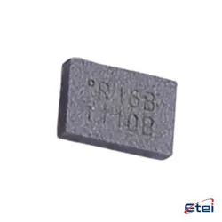
Abbildungen dienen nur als Referenz
HMC652LP2E
+StücklisteRF ATTENUATOR 2DB 50OHM 6TDFN
-
HerstellerAnalog Devices Inc.
-
Herstellerteil #HMC652LP2E
-
Datenblatt HMC652LP2E DataSheet
-
Paket DFN-6
-
Auf Lager4322
365 Tage Qualitätsgarantie
7*24 Stunden-Servicegarantie
90-Tage Kundendienstgarantie
Originalproduktgarantie
Spezifikationen
| Attribut | Wert |
| Package / Case | Strip |
| Part Status | Active |
| Attenuation Value | 2dB |
| Frequency Range | 0 Hz ~ 25 GHz |
| Impedance | 50 Ohms |
Übersicht
Description
Key features of the HMC652LP2E include its high linearity and low noise figure, which make it suitable for demanding applications such as cellular/3G infrastructure, WiMAX, and other wireless communication systems. The device is controlled via a serial interface, allowing for easy integration into digital systems. It comes in a 12-lead 2x2 mm leadless surface-mount package, facilitating efficient PCB layout and space-saving implementations. The HMC652LP2E is designed to offer robust performance with minimal external components, making it a popular choice for engineers looking to design flexible and efficient RF front-end circuits.
Equivalent
Features
1. Frequency Range: Operates between 0.3 GHz to 3.0 GHz, suitable for various RF applications.
2. Low Noise Figure: Typically around 1.2 dB, which is essential for maintaining signal integrity in low signal environments.
3. High Gain: Provides a typical gain of 12 dB, allowing for effective signal amplification.
4. Input and Output Impedance: Matches 50 ohms, ensuring compatibility with standard RF systems.
5. High Output IP3: Offers a high third-order intercept point of +31 dBm, enhancing linearity and intermodulation performance.
6. Supply Voltage: Operates at a supply voltage of +5V, making it easy to integrate into various systems.
7. Compact Package: Comes in a RoHS-compliant, leadless 2x2 mm SMT package, facilitating easy integration into PCB designs.
These features make the HMC652LP2E ideal for applications in wireless infrastructure, test equipment, and other RF communication systems.
Pinout
Here is a concise breakdown of its pin count and function:
- Pin 1 & Pin 10: Vdd (Positive Supply Voltage)
- Pin 2: RFIN (RF Input)
- Pin 3: N/C (No Connection, can be left floating or connected to GND)
- Pin 4 to Pin 9: A6 to A1 (Control Bits for Attenuation)
- Pin 5: RFOUT (RF Output)
- Pin 6, 7, 8, 9: Control pins A6, A5, A4, A3, A2, A1 (for setting attenuation levels)
- Pin 11 (Exposed Pad): GND (Ground, must be connected to the ground plane)
This configuration supports a wide frequency range and is typically used in RF and microwave applications.