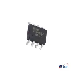
Abbildungen dienen nur als Referenz
IPD034N06N3G
+Stückliste-
HerstellerInfineon-Technologien
-
Herstellerteil #IPD034N06N3G
-
Auf Lager7484
365 Tage Qualitätsgarantie
7*24 Stunden-Servicegarantie
90-Tage Kundendienstgarantie
Originalproduktgarantie
Spezifikationen
| Attribut | Wert |
| Manufacturer | Infineon Technologies |
| Package / Case | TO-252-2(DPAK) |
| Operating Temperature | -55℃~+175℃ |
| Rds(on) | 3.4mΩ@10V,100A |
| Drain to Source Voltage (Vdss) | 60V |
| Pd - Power Dissipation | 167W |
| Current - Continuous Drain(Id) | 100A |
| Reverse Transfer Capacitance (Crss @ Vds) | 58pF@30V |
| Input Capacitance(Ciss @ Vds) | 11nF@30V |
| Type | 1 N-channel |
| Gate Threshold Voltage (Vgs(th) @ Id) | 4V |
Übersicht
Description
IPD034N06N3G is a power MOSFET (Metal-Oxide-Semiconductor Field-Effect Transistor) designed for high-efficiency applications. It is manufactured by Infineon Technologies and features a low on-resistance, allowing it to handle high current with minimal power loss. This N-channel MOSFET is particularly suitable for use in power management systems, DC-DC converters, and motor control applications.
Key specifications include a maximum drain-source voltage (VDS) of 60V, a continuous drain current (ID) of 34A, and a very low RDS(on), which enhances its efficiency during operation. The device is packaged in a DPAK (TO-252), providing effective thermal management and ease of integration into circuits.
The IPD034N06N3G is appreciated for its reliability and performance, making it a popular choice among engineers looking to optimize power efficiency in electronics.
Key specifications include a maximum drain-source voltage (VDS) of 60V, a continuous drain current (ID) of 34A, and a very low RDS(on), which enhances its efficiency during operation. The device is packaged in a DPAK (TO-252), providing effective thermal management and ease of integration into circuits.
The IPD034N06N3G is appreciated for its reliability and performance, making it a popular choice among engineers looking to optimize power efficiency in electronics.
Equivalent
The IPD034N06N3G is a N-channel MOSFET. Equivalent products include the IRF3205, FQP50N06, STP55NF06, and AOD6N06. Always verify specific electrical characteristics and ratings to ensure compatibility.
Features
The IPD034N06N3G is a N-channel MOSFET designed for high-efficiency power applications. Key features include:
1. Voltage Rating: 60V maximum drain-source voltage (V_DS).
2. Current Rating: Continuous drain current (I_D) of up to 34A, suitable for high-power applications.
3. R_DS(on): Low on-resistance of about 3.4 mΩ at V_GS = 10V, minimizing power losses during operation.
4. Gate Threshold Voltage (V_GS(th)): Typically ranges from 2V to 4V, facilitating easy drive with low-voltage logic.
5. Fast Switching: Optimized for high-speed switching applications, enhancing efficiency in converters and inverters.
6. Thermal Performance: Offers robust thermal characteristics with a low thermal resistance, allowing for effective heat dissipation.
7. Package: Available in a DPAK package, which provides a compact footprint and ease of mounting.
These features make the IPD034N06N3G suitable for a variety of applications, including DC-DC converters, motor drives, and power management systems.
1. Voltage Rating: 60V maximum drain-source voltage (V_DS).
2. Current Rating: Continuous drain current (I_D) of up to 34A, suitable for high-power applications.
3. R_DS(on): Low on-resistance of about 3.4 mΩ at V_GS = 10V, minimizing power losses during operation.
4. Gate Threshold Voltage (V_GS(th)): Typically ranges from 2V to 4V, facilitating easy drive with low-voltage logic.
5. Fast Switching: Optimized for high-speed switching applications, enhancing efficiency in converters and inverters.
6. Thermal Performance: Offers robust thermal characteristics with a low thermal resistance, allowing for effective heat dissipation.
7. Package: Available in a DPAK package, which provides a compact footprint and ease of mounting.
These features make the IPD034N06N3G suitable for a variety of applications, including DC-DC converters, motor drives, and power management systems.
Pinout
The IPD034N06N3G is an N-channel MOSFET from Infineon Technologies. It features a total of 5 pins. The pin configuration and their functions are as follows:
1. Gate (G) - This pin is used to control the MOSFET. A voltage applied here switches the device on or off.
2. Drain (D) - This pin is where the current exits the MOSFET when it is in the 'on' state, connecting to the load.
3. Source (S) - This pin connects to the ground or negative supply in a typical application.
The remaining two pins are usually for internal connections or not used in standard applications. The device is designed for high-efficiency applications, suitable for power management and switching applications. It has a low R_DS(on), making it ideal for reducing conduction losses.
1. Gate (G) - This pin is used to control the MOSFET. A voltage applied here switches the device on or off.
2. Drain (D) - This pin is where the current exits the MOSFET when it is in the 'on' state, connecting to the load.
3. Source (S) - This pin connects to the ground or negative supply in a typical application.
The remaining two pins are usually for internal connections or not used in standard applications. The device is designed for high-efficiency applications, suitable for power management and switching applications. It has a low R_DS(on), making it ideal for reducing conduction losses.
Manufacturer
The IPD034N06N3G is manufactured by Infineon Technologies AG, a global leader in semiconductor solutions. Infineon is headquartered in Neubiberg, Germany, and operates in various sectors including automotive, industrial power control, and security technologies. The company specializes in manufacturing a wide range of semiconductors, including power MOSFETs, microcontrollers, and sensors, which are essential for applications in electric vehicles, renewable energy, and smart home technologies. Infineon's products are known for their efficiency, reliability, and innovation, making them a key player in the semiconductor industry.
Application
The IPD034N06N3G is a N-channel MOSFET primarily used in power management applications. Its key areas include:
1. Power Supply Circuits - Efficient switching for DC-DC converters.
2. Motor Control - Driving DC motors and other inductive loads.
3. LED Lighting - Used in driver circuits for LED applications.
4. Battery Management Systems - Enhancing battery performance in power electronics.
5. Switching Regulators - For improved energy efficiency in power conversion.
6. Telecommunications - Power amplification and signal processing.
Its high efficiency and low on-resistance make it suitable for these applications.
1. Power Supply Circuits - Efficient switching for DC-DC converters.
2. Motor Control - Driving DC motors and other inductive loads.
3. LED Lighting - Used in driver circuits for LED applications.
4. Battery Management Systems - Enhancing battery performance in power electronics.
5. Switching Regulators - For improved energy efficiency in power conversion.
6. Telecommunications - Power amplification and signal processing.
Its high efficiency and low on-resistance make it suitable for these applications.
Package
The IPD034N06N3G is packaged in a TO-220 format, which is a type of metal package commonly used for power transistors and MOSFETs. This package provides efficient heat dissipation and is suitable for high-power applications.