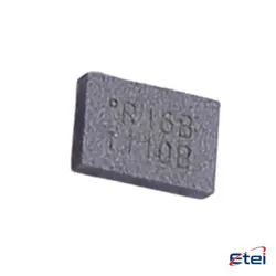
Abbildungen dienen nur als Referenz
LM555CM/NOPB
+StücklisteIC OSC SGL TIMER 100KHZ 8-SOIC
-
HerstellerTexas Instruments
-
Herstellerteil #LM555CM/NOPB
-
Datenblatt LM555CM/NOPB DataSheet
-
Paket SOIC-8
-
Auf Lager8120
365 Tage Qualitätsgarantie
7*24 Stunden-Servicegarantie
90-Tage Kundendienstgarantie
Originalproduktgarantie
Spezifikationen
| Attribut | Wert |
| Supplier | Texas Instruments |
| Package / Case | Tube |
| Part Status | Active |
| Type | 555 Type, Timer/Oscillator (Single) |
| Frequency | 100kHz |
| Voltage - Supply | 4.5V ~ 16V |
| Supply Current | 10 mA |
| Operating Temperature | 0°C ~ 70°C |
| Supplier Device Package | 8-SOIC |
Übersicht
Description
Equivalent
Features
1. Timing Range: It can operate in both astable and monostable modes, offering a wide timing range from microseconds to hours.
2. Supply Voltage: Works effectively with a supply voltage ranging from 4.5V to 15V, making it compatible with standard TTL and CMOS logic levels.
3. Output Compatibility: Provides a high output current capability, typically up to 200 mA, allowing it to drive loads directly.
4. Temperature Stability: Exhibits good temperature stability, with minimal variation in timing over a wide temperature range (-40°C to 85°C).
5. Low Power Consumption: Features low power consumption, making it suitable for battery-operated devices.
6. Adjustable Duty Cycle: Allows the duty cycle to be adjusted, which is useful in applications requiring pulse-width modulation (PWM).
7. Pin Configuration: Comes in an 8-pin package, simplifying integration into circuits.
These features make the LM555CM/NOPB a popular choice for applications like oscillators, pulse generation, time delays, and more.
Pinout
1. GND (Pin 1): Ground reference voltage, connected to the 0V power supply.
2. TRIG (Pin 2): Trigger input, starts the timing interval; a low voltage here (<1/3 VCC) causes the output to go high.
3. OUT (Pin 3): Output, delivers the timer's signal, either high or low, depending on the configuration.
4. RESET (Pin 4): Reset input, active low; takes precedence over other inputs and resets the timing interval when low.
5. CTRL (Pin 5): Control voltage, used to adjust the threshold and trigger levels; typically connected to ground via a capacitor for noise filtering.
6. THRS (Pin 6): Threshold, ends the timing interval; when voltage exceeds 2/3 VCC, the output goes low.
7. DISCH (Pin 7): Discharge, connected to the timing capacitor; used to discharge it in astable mode.
8. VCC (Pin 8): Supply voltage, the positive power supply terminal.
This IC is renowned for its flexibility and is commonly employed in applications like timers, pulse generation, and sequencers.
Manufacturer
Application
1. Astable Multivibrator: Generates continuous square wave signals for clock pulses or LED flashers.
2. Monostable Multivibrator: Provides single pulse output for timers, delay circuits, or debounce switches.
3. Pulse Width Modulation (PWM): Controls motor speed or brightness of lights.
4. Frequency Divider: Reduces frequency of input signals for frequency division applications.
5. Tone Generation: Used in audio applications to create sound effects or alert tones.
6. Voltage-Controlled Oscillator (VCO): Used in signal generation where frequency is controlled by an input voltage.
These features make it ideal for use in consumer electronics, automotive, industrial, and communication systems.