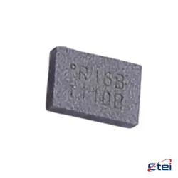
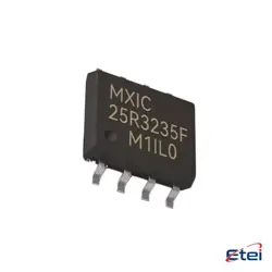
Abbildungen dienen nur als Referenz
M74ACT251D
+StücklisteMULTIPLEXER, ACT SERIES, 1-FUNC
-
HerstellerOnsemi
-
Herstellerteil #M74ACT251D
-
Auf Lager8903
365 Tage Qualitätsgarantie
7*24 Stunden-Servicegarantie
90-Tage Kundendienstgarantie
Originalproduktgarantie
Spezifikationen
| Attribut | Wert |
| Package / Case | 1 |
| Series | Bulk |
| Type | Active |
Übersicht
Description
The M74ACT251D is an integrated circuit from the 74ACT series, which is a family of advanced high-speed CMOS devices with TTL-compatible inputs. This specific IC is an 8-input multiplexer with a 3-state output. It allows the selection of one of eight binary inputs to be routed to a single output line, based on a 3-bit address input. This device is particularly useful in applications requiring the routing of multiple data lines to a single line, such as in data routing, communication systems, and signal multiplexing.
Key features of the M74ACT251D include high-speed operation, low power consumption due to CMOS technology, and compatibility with TTL logic levels. Additionally, the output enable pin allows for the output to be placed in a high-impedance state, facilitating easy interfacing with bus-oriented systems. The device is packaged in a standard dual in-line or surface-mount configuration, making it versatile for various electronic applications.
Key features of the M74ACT251D include high-speed operation, low power consumption due to CMOS technology, and compatibility with TTL logic levels. Additionally, the output enable pin allows for the output to be placed in a high-impedance state, facilitating easy interfacing with bus-oriented systems. The device is packaged in a standard dual in-line or surface-mount configuration, making it versatile for various electronic applications.
Equivalent
The M74ACT251D is an 8-channel digital multiplexer. Equivalent products include:
1. 74ACT251 from various manufacturers.
2. CD74ACT251 from Texas Instruments.
3. SN74ACT251 from Texas Instruments.
4. MC74ACT251 from ON Semiconductor.
Ensure compatibility by checking the datasheets for specific electrical characteristics and pin configurations, as they might vary slightly between manufacturers.
1. 74ACT251 from various manufacturers.
2. CD74ACT251 from Texas Instruments.
3. SN74ACT251 from Texas Instruments.
4. MC74ACT251 from ON Semiconductor.
Ensure compatibility by checking the datasheets for specific electrical characteristics and pin configurations, as they might vary slightly between manufacturers.
Features
The M74ACT251D is an octal 3-state buffer/line driver with several notable features:
1. High-Speed CMOS Technology: It uses advanced CMOS technology for high-speed data processing and low power consumption.
2. Wide Supply Voltage Range: Supports a wide range of supply voltages, typically between 4.5V and 5.5V.
3. 3-State Outputs: Incorporates three-state outputs, allowing the user to connect multiple outputs to a single bus line without interference.
4. Low Power Dissipation: Designed for minimal power consumption, making it suitable for battery-powered applications.
5. TTL Compatibility: The inputs are TTL-compatible, ensuring compatibility with digital devices and systems.
6. High Drive Capability: Capable of driving significant capacitive loads, making it ideal for driving multiple inputs.
7. Latch-Up Performance: Exhibits excellent latch-up performance, ensuring reliability in various operational conditions.
8. ESD Protection: Built-in electrostatic discharge protection to safeguard against voltage spikes.
These features make the M74ACT251D suitable for use in high-speed digital applications, including memory systems, microprocessor systems, and data communication systems.
1. High-Speed CMOS Technology: It uses advanced CMOS technology for high-speed data processing and low power consumption.
2. Wide Supply Voltage Range: Supports a wide range of supply voltages, typically between 4.5V and 5.5V.
3. 3-State Outputs: Incorporates three-state outputs, allowing the user to connect multiple outputs to a single bus line without interference.
4. Low Power Dissipation: Designed for minimal power consumption, making it suitable for battery-powered applications.
5. TTL Compatibility: The inputs are TTL-compatible, ensuring compatibility with digital devices and systems.
6. High Drive Capability: Capable of driving significant capacitive loads, making it ideal for driving multiple inputs.
7. Latch-Up Performance: Exhibits excellent latch-up performance, ensuring reliability in various operational conditions.
8. ESD Protection: Built-in electrostatic discharge protection to safeguard against voltage spikes.
These features make the M74ACT251D suitable for use in high-speed digital applications, including memory systems, microprocessor systems, and data communication systems.
Pinout
The M74ACT251D is a high-speed CMOS 8-channel multiplexer with a 3-state output. It is part of the 74ACT series, which is an advanced CMOS series compatible with TTL logic levels. The M74ACT251D typically comes in a 16-pin dual in-line package (DIP).
Here is a brief description of its pin function:
1. Pins 1-3 (A, B, C): Select inputs for choosing one of the eight data inputs.
2. Pins 4-11 (D0-D7): Data inputs. These are the eight channels from which the device selects one to be transmitted to the output.
3. Pin 12 (Y): The multiplexed output, which reflects the logic level of the selected data input.
4. Pin 13 (/G): Output enable. When low, the output is enabled; when high, the output is in high impedance (3-state mode).
5. Pin 14 (W): Active low input. Used to clear the device.
6. Pin 15 (VCC): Power supply pin for the device.
7. Pin 16 (GND): Ground pin.
These pin assignments are standard for the M74ACT251D and are used to facilitate its function as a multiplexer, allowing any one of eight data inputs to be routed to a single output line.
Here is a brief description of its pin function:
1. Pins 1-3 (A, B, C): Select inputs for choosing one of the eight data inputs.
2. Pins 4-11 (D0-D7): Data inputs. These are the eight channels from which the device selects one to be transmitted to the output.
3. Pin 12 (Y): The multiplexed output, which reflects the logic level of the selected data input.
4. Pin 13 (/G): Output enable. When low, the output is enabled; when high, the output is in high impedance (3-state mode).
5. Pin 14 (W): Active low input. Used to clear the device.
6. Pin 15 (VCC): Power supply pin for the device.
7. Pin 16 (GND): Ground pin.
These pin assignments are standard for the M74ACT251D and are used to facilitate its function as a multiplexer, allowing any one of eight data inputs to be routed to a single output line.
Manufacturer
The M74ACT251D is manufactured by STMicroelectronics. STMicroelectronics is a global company that specializes in the design, development, manufacturing, and marketing of a wide range of semiconductor products. Founded in 1987, it is headquartered in Geneva, Switzerland, and is one of the largest semiconductor companies in the world. STMicroelectronics serves various markets, including automotive, industrial, personal electronics, and communications equipment, by providing components and solutions that drive innovation and efficiency across these sectors.
Application
The M74ACT251D is a high-speed CMOS 8-channel multiplexer/demultiplexer. It is typically used in digital signal processing, data multiplexing, and communication systems. Common applications include logic function generation, data routing, and selectable data distribution in microprocessor systems. It's also used in network switches for channel selection and in testing equipment for routing different signals. Its ability to handle high-speed data makes it suitable for applications requiring fast data processing and switching.
Package
The M74ACT251D is an integrated circuit with a 16-lead small outline package (SOP). This package type is designed for surface-mount technology, offering a compact and efficient solution for electronic applications.