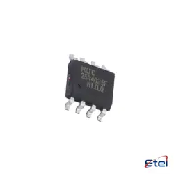
Abbildungen dienen nur als Referenz
MRFE6VS25NR1
+StücklisteRF MOSFET LDMOS 50V TO270-2
-
HerstellerNXP USA Inc.
-
Herstellerteil #MRFE6VS25NR1
-
Auf Lager2681
365 Tage Qualitätsgarantie
7*24 Stunden-Servicegarantie
90-Tage Kundendienstgarantie
Originalproduktgarantie
Spezifikationen
| Attribut | Wert |
| Part Status | Obsolete |
| Technology | LDMOS |
| Frequency | 512MHz |
| Gain | 25.4dB |
| Voltage - Test | 50 V |
| Current - Test | 10 mA |
| Power - Output | 25W |
| Voltage - Rated | 133 V |
| Mounting Type | Surface Mount |
| Package / Case | TO-270AA |
| Supplier Device Package | TO-270-2 |
| Base Product Number | MRFE6 |
Übersicht
Description
The MRFE6VS25NR1 is a high-performance RF power transistor designed for use in various applications, including telecommunications and industrial RF systems. It is part of the NXP Semiconductors' product line and is optimized for high linearity and efficiency, making it suitable for use in amplifiers operating within the UHF and VHF frequency ranges.
Key features include a wide frequency range, high output power capacity, and robust thermal performance, ensuring reliable operation under demanding conditions. The transistor typically comes in a rugged package that facilitates ease of integration into circuit designs.
Its specifications often include a high gain, low thermal resistance, and excellent power-added efficiency, making it ideal for both linear and nonlinear applications. Overall, the MRFE6VS25NR1 represents a versatile solution for engineers looking to enhance RF amplification in various systems.
Key features include a wide frequency range, high output power capacity, and robust thermal performance, ensuring reliable operation under demanding conditions. The transistor typically comes in a rugged package that facilitates ease of integration into circuit designs.
Its specifications often include a high gain, low thermal resistance, and excellent power-added efficiency, making it ideal for both linear and nonlinear applications. Overall, the MRFE6VS25NR1 represents a versatile solution for engineers looking to enhance RF amplification in various systems.
Equivalent
The MRFE6VS25NR1 is a N-Channel RF power MOSFET. Equivalent products include the MRFE6VS25NR1P, NXP's BLF578XR, and the STMicroelectronics STW25NM60. Other alternatives might include devices from manufacturers like Infineon, Vishay, and Toshiba, depending on specific application requirements such as frequency range, power output, and packaging. Always check datasheets for compatibility.
Features
The MRFE6VS25NR1 is a high-performance RF power transistor designed for RF applications. Key features include:
1. Power Output: Capable of delivering up to 25 watts of output power in the VHF/UHF frequency range.
2. Frequency Range: Operates efficiently from 30 MHz to 1 GHz, making it suitable for various communications applications.
3. High Gain: Provides a high power gain, typically around 16 dB, facilitating effective signal amplification.
4. Class AB Operation: Designed for Class AB operation, balancing efficiency and linearity for applications like amplifiers.
5. Thermal Stability: Features a robust thermal design, ensuring reliability under high-temperature conditions.
6. Package Type: Available in a ceramic package, enhancing durability and performance.
7. Low Distortion: Delivers low intermodulation distortion, ensuring high-quality signal processing.
These characteristics make the MRFE6VS25NR1 ideal for TV transmitters, communication systems, and other RF applications where reliability and performance are critical.
1. Power Output: Capable of delivering up to 25 watts of output power in the VHF/UHF frequency range.
2. Frequency Range: Operates efficiently from 30 MHz to 1 GHz, making it suitable for various communications applications.
3. High Gain: Provides a high power gain, typically around 16 dB, facilitating effective signal amplification.
4. Class AB Operation: Designed for Class AB operation, balancing efficiency and linearity for applications like amplifiers.
5. Thermal Stability: Features a robust thermal design, ensuring reliability under high-temperature conditions.
6. Package Type: Available in a ceramic package, enhancing durability and performance.
7. Low Distortion: Delivers low intermodulation distortion, ensuring high-quality signal processing.
These characteristics make the MRFE6VS25NR1 ideal for TV transmitters, communication systems, and other RF applications where reliability and performance are critical.
Pinout
The MRFE6VS25NR1 is a high-power RF MOSFET designed for use in RF amplification applications. It typically comes in a surface-mount package with a pin count of 4. The pin functions are as follows:
1. Gate (G) - Controls the switching of the MOSFET and modulates the RF signal.
2. Drain (D) - The terminal through which the output signal is taken; it connects to the load.
3. Source (S) - The terminal connected to the ground or common reference point in the circuit.
4. Source (S) - The second source pin, which is often used to improve thermal performance and current handling.
This device is optimized for applications in the VHF and UHF frequency ranges and is capable of delivering high power efficiency.
1. Gate (G) - Controls the switching of the MOSFET and modulates the RF signal.
2. Drain (D) - The terminal through which the output signal is taken; it connects to the load.
3. Source (S) - The terminal connected to the ground or common reference point in the circuit.
4. Source (S) - The second source pin, which is often used to improve thermal performance and current handling.
This device is optimized for applications in the VHF and UHF frequency ranges and is capable of delivering high power efficiency.
Manufacturer
The MRFE6VS25NR1 is manufactured by NXP Semiconductors, a global semiconductor company known for its advanced technology in various applications. NXP specializes in high-performance mixed signal and standard product solutions, including radio frequency (RF) power transistors, microcontrollers, automotive electronics, and secure connectivity solutions. The company serves multiple markets, including automotive, industrial, mobile, and consumer electronics. NXP's products are widely used in applications such as wireless communication, smart devices, and automotive safety systems, emphasizing innovation and quality in semiconductor manufacturing.
Application
The MRFE6VS25NR1 is a high-power RF transistor primarily used in various applications such as:
1. Telecommunications: For RF amplification in base stations and cellular infrastructure.
2. Broadcasting: In TV and radio transmitters for high-efficiency signal transmission.
3. Industrial Heating: In RF heating and welding systems.
4. Aerospace and Defense: For radar and communication systems requiring high power and reliability.
5. Medical Equipment: In RF applications such as MRI and RF ablation.
Its high power handling and efficiency make it suitable for these demanding applications.
1. Telecommunications: For RF amplification in base stations and cellular infrastructure.
2. Broadcasting: In TV and radio transmitters for high-efficiency signal transmission.
3. Industrial Heating: In RF heating and welding systems.
4. Aerospace and Defense: For radar and communication systems requiring high power and reliability.
5. Medical Equipment: In RF applications such as MRI and RF ablation.
Its high power handling and efficiency make it suitable for these demanding applications.
Package
The MRFE6VS25NR1 is packaged in a METAL casing, specifically a TO-247 style package. This packaging provides effective heat dissipation for high-power applications.