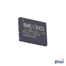
Abbildungen dienen nur als Referenz
TL594CDR
+StücklisteIC REG CTRLR MULT TOP 16SOIC
-
HerstellerTexas Instruments
-
Herstellerteil #TL594CDR
-
Datenblatt TL594CDR DataSheet
-
Paket SOIC-16
-
Auf Lager6101
365 Tage Qualitätsgarantie
7*24 Stunden-Servicegarantie
90-Tage Kundendienstgarantie
Originalproduktgarantie
Spezifikationen
| Attribut | Wert |
| Package / Case | Tape & Reel (TR),Cut Tape (CT),Bulk |
| Part Status | Active |
| Output Type | Transistor Driver |
| Function | Step-Up, Step-Down, Step-Up/Step-Down |
| Output Configuration | Positive |
| Topology | Buck, Boost, Flyback, Forward Converter, Full-Bridge, Half-Bridge, Push-Pull |
| Number of Outputs | 2 |
| Output Phases | 1 |
| Voltage - Supply (Vcc/Vdd) | 7V ~ 40V |
| Frequency - Switching | 1kHz ~ 300kHz |
| Duty Cycle(Max) | 97% |
| Synchronous Rectifier | No |
| Clock Sync | No |
| Control Features | Dead Time Control, Frequency Control |
| Operating Temperature | 0°C ~ 70°C (TA) |
| Mounting Type | Surface Mount |
Übersicht
Description
Key functionalities of the TL594CDR include adjustable dead time, which helps prevent overlap in the switching of the transistors, and a wide voltage range (7V to 40V) for various applications. The device supports both voltage-mode and current-mode control, making it adaptable to different system requirements.
The TL594CDR is suitable for driving both NPN and PNP transistors, providing further flexibility in design. It operates in a temperature range from -40°C to +125°C, making it reliable in various environmental conditions. Applications include switch-mode power supplies, DC-DC converters, and motor speed controls. The device's reliability and cost-effectiveness make it a popular choice in the electronics industry.
Equivalent
Features
1. Dual PWM Outputs: Allows for control of two output channels, enabling flexibility in design and application.
2. Voltage Control: Provides precise voltage regulation through an internal reference of 5V.
3. Adjustable Dead Time Control: Offers the ability to control the dead time to minimize power losses and improve efficiency.
4. Error Amplifier: Includes an error amplifier for error signal processing and enhanced control accuracy.
5. Undervoltage Lockout: Protects the device by disabling the output when the supply voltage is too low.
6. Built-in Oscillator: Provides a frequency range from 1 kHz to 300 kHz, which is adjustable via external components.
7. Soft Start Capability: Gradually increases the output voltage, protecting circuits from inrush currents.
8. Current Limit Control: Prevents overcurrent conditions by limiting the peak output current.
9. Compact Package: Available in a SOIC-16 package, making it suitable for space-constrained applications.
These features make the TL594CDR ideal for efficient and reliable power conversion in various electronic systems.
Pinout
Here is a concise overview of its pin functions:
1. GND (Pin 7): Ground reference for the IC.
2. VCC (Pin 12): Supply voltage input.
3. COMP (Pin 3): Compensation pin for error amplifier to stabilize the control loop.
4. FEEDBACK (Pin 2): Input to the error amplifier.
5. DTC (Pin 4): Dead-time control, adjusts the off-time in PWM cycle.
6. CT (Pin 5): Timing capacitor pin for the oscillator.
7. RT (Pin 6): Timing resistor pin for the oscillator.
8. C1, C2 (Pins 13, 15): Outputs for driving external transistors.
9. E1, E2 (Pins 14, 16): Emitter connections for output transistors.
10. VREF (Pin 8): Reference voltage output.
11. INV INPUT (Pin 1): Inverting input to the error amplifier.
12. NC (Pin 11): No connection.
13. OUTPUT CONTROL (Pin 9): Selects output configuration.
14. SYNC (Pin 10): Synchronizes multiple devices.
These pins facilitate PWM control functions, including voltage regulation, timing, and output control.
Manufacturer
Application
1. Switching Power Supplies: It regulates voltage and current efficiently in converters and inverters.
2. DC-DC Converters: Used for voltage regulation in buck, boost, and buck-boost converters.
3. Motor Control: Provides precise control over motor speed and torque.
4. Battery Chargers: Used for managing charging cycles and maintaining battery health.
5. LED Drivers: Controls LED brightness and efficiency in lighting applications.
Its features like dual-output control, adjustable dead-time, and on-chip error amplifiers make it suitable for complex power management tasks.