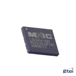
Abbildungen dienen nur als Referenz
TLV9064IRUCR
+Stückliste-
HerstellerTexas Instruments
-
Herstellerteil #TLV9064IRUCR
-
Auf Lager2282
365 Tage Qualitätsgarantie
7*24 Stunden-Servicegarantie
90-Tage Kundendienstgarantie
Originalproduktgarantie
Spezifikationen
| Attribut | Wert |
| Package | Tape & Reel (TR),Cut Tape (CT) |
| ProductStatus | Active |
| AmplifierType | CMOS |
| NumberofCircuits | 4 |
| OutputType | Rail-to-Rail |
| SlewRate | 6.5V/µs |
| GainBandwidthProduct | 10 MHz |
| Current-InputBias | 0.5 pA |
| Voltage-InputOffset | 300 µV |
| Current-Supply | 538µA (x4 Channels) |
| Current-Output/Channel | 50 mA |
| Voltage-SupplySpan(Min) | 1.8 V |
| Voltage-SupplySpan(Max) | 5.5 V |
| OperatingTemperature | -40°C ~ 125°C (TA) |
| MountingType | Surface Mount |
| Package/Case | 14-XFQFN |
Übersicht
Description
The TLV9064IRUCR is a quad-channel operational amplifier (op-amp) developed by Texas Instruments. It is designed for a wide range of general-purpose applications, offering a good balance between performance and cost. The op-amp features low offset voltage and low input bias current, making it suitable for precision analog signal processing tasks. It operates on a supply voltage range of 1.8V to 5.5V, which provides flexibility for integration in various battery-powered and low-voltage systems.
Key specifications include a gain bandwidth product of 10 MHz, enabling it to handle relatively high-frequency applications compared to other general-purpose op-amps. It also boasts a low noise density, contributing to clean signal amplification in audio or sensor applications. The device is housed in a compact UQFN package, providing an efficient space-saving solution for circuit board designs. With its robust performance and efficient power consumption, the TLV9064IRUCR is well-suited for applications in consumer electronics, industrial equipment, and automotive systems where reliable and accurate signal amplification is required.
Key specifications include a gain bandwidth product of 10 MHz, enabling it to handle relatively high-frequency applications compared to other general-purpose op-amps. It also boasts a low noise density, contributing to clean signal amplification in audio or sensor applications. The device is housed in a compact UQFN package, providing an efficient space-saving solution for circuit board designs. With its robust performance and efficient power consumption, the TLV9064IRUCR is well-suited for applications in consumer electronics, industrial equipment, and automotive systems where reliable and accurate signal amplification is required.
Equivalent
The TLV9064IRUCR is a quad operational amplifier by Texas Instruments. Equivalent products might include the LM324 series, TL074 series, and OPA4134 by Texas Instruments, or similar quad op-amps from manufacturers like Analog Devices (e.g., AD8608) and STMicroelectronics (e.g., TS924). When selecting an equivalent, it is crucial to compare specifications such as supply voltage range, bandwidth, input offset voltage, and package type to ensure compatibility with your application.
Features
The TLV9064IRUCR is a quad-channel operational amplifier from Texas Instruments. It features low power consumption with a supply current of approximately 320 µA per channel. This device operates over a wide supply voltage range from 1.8 V to 5.5 V, making it versatile for various applications. It offers a high slew rate of 12 V/µs and a gain bandwidth product of 5 MHz, providing fast signal processing capabilities.
The TLV9064IRUCR boasts rail-to-rail input and output, which enhances its performance in low-voltage applications by maximizing the signal swing. It offers low input bias current and offset voltage, ensuring precision in signal amplification. The device is designed for stability and includes internal phase compensation, which simplifies its use in a wide range of circuits.
The operational amplifier is housed in a compact QFN package, facilitating space-saving designs in electronics. Typical applications for the TLV9064IRUCR include sensor signal conditioning, active filters, and control systems. Its combination of features makes it suitable for portable and battery-powered devices.
The TLV9064IRUCR boasts rail-to-rail input and output, which enhances its performance in low-voltage applications by maximizing the signal swing. It offers low input bias current and offset voltage, ensuring precision in signal amplification. The device is designed for stability and includes internal phase compensation, which simplifies its use in a wide range of circuits.
The operational amplifier is housed in a compact QFN package, facilitating space-saving designs in electronics. Typical applications for the TLV9064IRUCR include sensor signal conditioning, active filters, and control systems. Its combination of features makes it suitable for portable and battery-powered devices.
Pinout
The TLV9064IRUCR is a quad operational amplifier (op-amp) from Texas Instruments. It typically features a 14-pin configuration. The primary function of this device is to amplify voltage signals, serving in various applications such as active filters, integrators, summing amplifiers, and general-purpose analog signal processing.
Here is a brief overview of its pin configuration:
1. Pin 1: Output of Op-Amp 1
2. Pin 2: Inverting Input of Op-Amp 1
3. Pin 3: Non-Inverting Input of Op-Amp 1
4. Pin 4: Supply Voltage (V- or GND)
5. Pin 5: Non-Inverting Input of Op-Amp 2
6. Pin 6: Inverting Input of Op-Amp 2
7. Pin 7: Output of Op-Amp 2
8. Pin 8: Output of Op-Amp 3
9. Pin 9: Inverting Input of Op-Amp 3
10. Pin 10: Non-Inverting Input of Op-Amp 3
11. Pin 11: Non-Inverting Input of Op-Amp 4
12. Pin 12: Inverting Input of Op-Amp 4
13. Pin 13: Output of Op-Amp 4
14. Pin 14: Supply Voltage (V+)
This configuration allows it to be used in various multi-channel analog processing applications.
Here is a brief overview of its pin configuration:
1. Pin 1: Output of Op-Amp 1
2. Pin 2: Inverting Input of Op-Amp 1
3. Pin 3: Non-Inverting Input of Op-Amp 1
4. Pin 4: Supply Voltage (V- or GND)
5. Pin 5: Non-Inverting Input of Op-Amp 2
6. Pin 6: Inverting Input of Op-Amp 2
7. Pin 7: Output of Op-Amp 2
8. Pin 8: Output of Op-Amp 3
9. Pin 9: Inverting Input of Op-Amp 3
10. Pin 10: Non-Inverting Input of Op-Amp 3
11. Pin 11: Non-Inverting Input of Op-Amp 4
12. Pin 12: Inverting Input of Op-Amp 4
13. Pin 13: Output of Op-Amp 4
14. Pin 14: Supply Voltage (V+)
This configuration allows it to be used in various multi-channel analog processing applications.
Manufacturer
The TLV9064IRUCR is manufactured by Texas Instruments Incorporated (TI). Texas Instruments is a global semiconductor company that designs and produces a wide range of electronic components and integrated circuits. They serve various industries, including consumer electronics, automotive, industrial, and communications. TI is well-known for its innovation in analog and embedded processing technologies.
Application
The TLV9064IRUCR is a quad operational amplifier known for its low power consumption and wide bandwidth. Its application areas include:
1. Instrumentation: Used in precision measurement devices due to its low offset voltage.
2. Consumer Electronics: Suitable for audio processing and signal conditioning.
3. Industrial Automation: Used in sensor signal amplification and data acquisition systems.
4. Medical Devices: Ideal for portable medical equipment due to low power requirements.
5. Communication Systems: Utilized in RF amplification and filters.
Its small size and versatility make it suitable for a wide range of applications that require efficient signal processing.
1. Instrumentation: Used in precision measurement devices due to its low offset voltage.
2. Consumer Electronics: Suitable for audio processing and signal conditioning.
3. Industrial Automation: Used in sensor signal amplification and data acquisition systems.
4. Medical Devices: Ideal for portable medical equipment due to low power requirements.
5. Communication Systems: Utilized in RF amplification and filters.
Its small size and versatility make it suitable for a wide range of applications that require efficient signal processing.
Package
The TLV9064IRUCR is a quad operational amplifier from Texas Instruments, packaged in a 14-pin WQFN (RTW) package. This package type is compact and designed for space-constrained applications, offering features like low quiescent current and low offset voltage.